Portfolio
Load test of a composite steel-concrete high-capacity deck
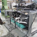
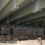 The specimen is a composite steel-concrete deck for a parking lot with a net span of 18.50 m. In this case, we could not perform the test with loaded trucks because of low head-room between decks: as an inexpensive and effective alternative, the Structures and Materials Testing Laboratory proposed the use of a pair of jacks of 1000 kN capacity to apply the load. This was done using high-strength threaded rods through holes in the top slab. The load was applied at two points at 3.20 m from the centerline on each side, at one-third of the span. A pair of horizontal bars was placed to link the two rods above the slab. Devices were arranged to determine longitudinal and transverse deformation, so that the transverse force on the slab could be determined.
Failure tests on rock-fall protection kits
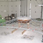
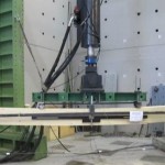
Quasi-static transverse tests were performed on torpedo net or panels made of steel cables. The load was applied using a concrete spherical cap connected to an electro-hydraulic actuator of 1000 kN capacity, restrained by a reaction frame with 2000 kN capacity and designed by MSTL. The test procedure, with slight modifications, followed code UNI 11437:2012 “Testing for networks covering slopes”. The panels were constrained at edges with a multiple steel cables, in number to ensure adequate tensile strength. At the corners, the panel was fastened to metal anchorages, two of which were fitted with load cells of capacity 1000 kN. Pairs of wire transducers were connected to the edges of the panel, to allow determination of the cable path, which was function of the applied load. The displacement was measured twice, by acting on the bars that connected the spherical cap to the actuator, until panel failure or until constraining bars reached their yield load.
Load test on prefabricated wall
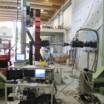
A load test was performed on a precast reinforced concrete wall. The sample, weighing about 15 t, was produced in a factory and then transported to the laboratory as an oversize load. Using the two 10-ton overhead cranes at MSTL and a steel distribution system, the sample was lifted and placed in front of the reaction wall. It was then fastened down with high-strength bars and a lateral force was applied, increasing the load magnitude until the capacity of the system force distribution system was reached. Displacement transducers recorded the transverse deformation of the wall, while the lateral load applied by an actuator with 1000 kN of capacity was acquired with load cells installed on the actuator itself. The test was stopped when the yield strength of the distribution system was reached.
Load test on wind turbine
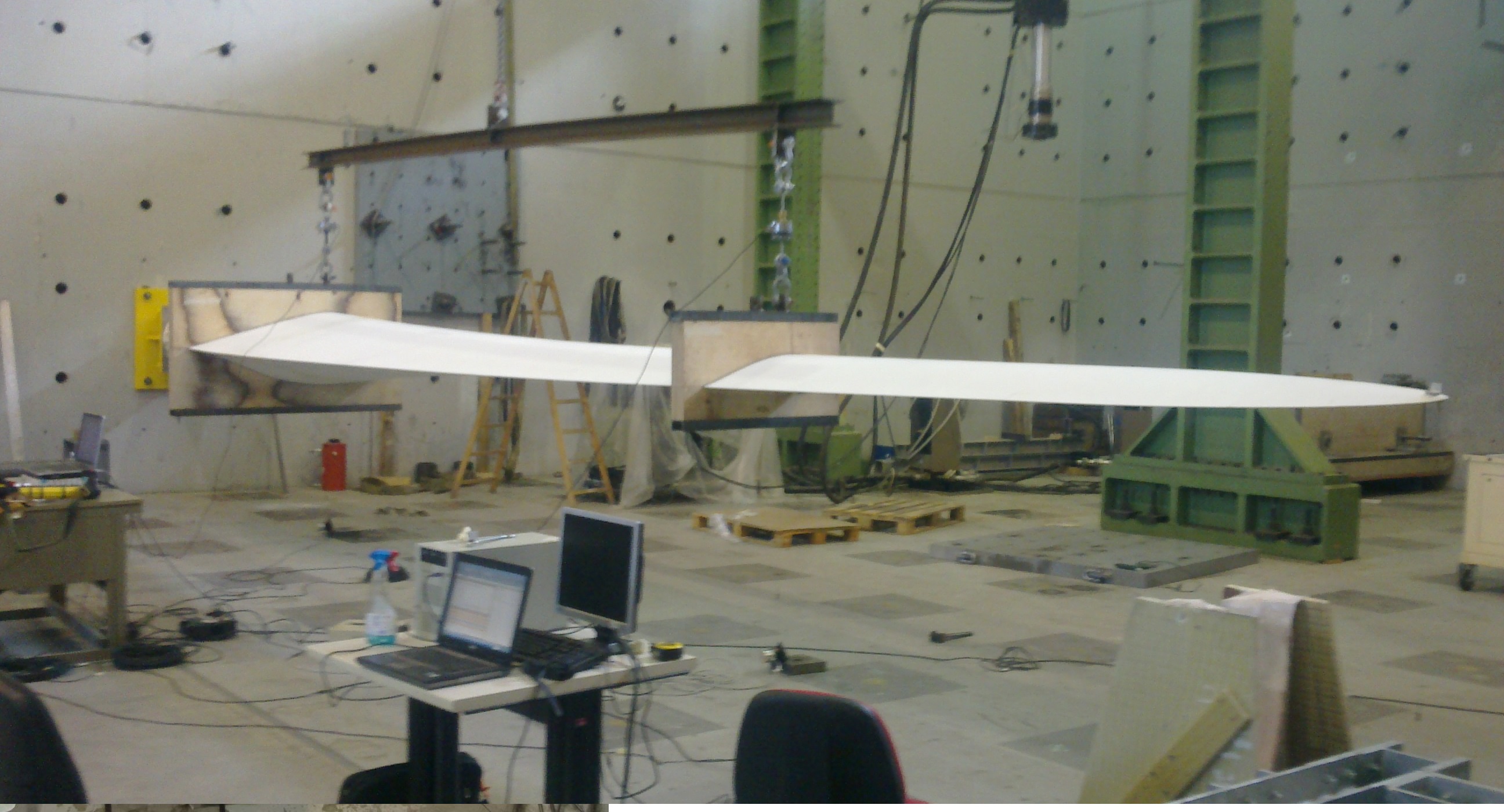
Static and dynamic tests were carried out on a new turbine blade with the aim of characterizing its stiffness and natural frequencies. The reason for this test is that natural blade vibration frequencies must not be close to those of the turbine tower. In cooperation with the customer, the laboratory developed a finite element model of the plate connecting the blade to the reaction wall; this to ensure that the plate was adequately rigid with respect to the fundamental frequency as numerically estimated. We carried out preliminary vibration tests first, and then static load and dynamic tests. The comparison between the frequencies recorded before and after the static load test helped to avert invisible structural damage.
Dynamic tests were carried out using PCB piezoelectric accelerometers at sampling frequencies of 1 kHz sample rate. The acquisition units were type NI PCI 4472B, allowing data acquisition at sample rates of up to 40 kHz.
The static tests were performed by applying the load at two points using an overhead crane. Two class-1 strain gauge cells measured the load, while the displacement was acquired by wire transducers. The data was recorded by an acquisition unit type HBM Spider 8.
Load test on the body of F1 car for “Toro Rosso”
A static test was performed on the carbon-fiber body of an F1 car. In this test, performed before a crash test, lateral load was applied at points close to the driver’s cockpit, and the test was performed using a plate provided by the customer.
The test was carried out by placing the vehicle on one side, and then by applying the load from above using an electro-hydraulic actuator, namely 244 MTS of capacity 1000 kN. The actuator was coupled to a FlexTest 60 controller, which was then connected to several AEP strain gauges, property of MSTL, in order to detect the deformation of points within the body.
The test was performed under displacement control , by imposing load steps of increasing amplitude and reaching the preset values in the load control , with strict limits on the displacement expected . The experimental values were compared with the corresponding calculated with a finite element model prepared by Scuderia Toro Rosso.
Load tests on footbridges

The laboratory has carried out numerous static and dynamic tests on bridges and footbridges. Here we cite those carried out on the footbridges at San Michele and Nomi (TN), both had span longer than 100 m, without intermediate piles in the riverbed.
In the two cases, the measurements were made using both a dumpy level and displacement transducers, with data recorded by acquisition units. The load was applied by filling boxes, waterproofed using plastic sheets, and filled by pumping water from the aqueduct or from the river, with the help of the fire brigade. The sequence of loading and unloading enabled us to maximize the shear and bending stresses in the deck and in the other bridge components.
The static load tests were followed by vibration tests aiming to characterize the natural frequencies of the structure, verifying the maximum transverse acceleration and allowing the dampers to be tuned.
Non-destructive testing of masonry
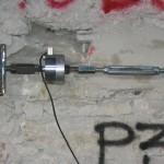
On-site sonic tests and tests involving flat jacks were carried out on a school building, to characterize the masonry properties. After removing plaster from the walls, sonic tests were carried out to obtain the average wave speed. At the same position, we then carried out tests with single and double flat jacks, using a pressure gauge with high resolution. A notch in the wall was made with a special circular saw supplied by the laboratory.
In the same masonry element, we anchored pairs of threaded rods using a chemical adhesive. The shear behavior of the rods was then tested. For this test we made a pair of metal plates, which were then tensioned using a threaded bar connected to a load cell. The applied load was acquired while a displacement transducer recorded the corresponding displacement. This allowed us to graph the load-displacement curve for the glued bars, in the range of the load involved.
Tests on wood panels for walls
The laboratory has carried out numerous tests on various types of timber walls: Xlam (glued or nailed), frames, etc. The results obtained by performing bending and transverse shear tests on the median plane and in the plane were used to achieve the “CE mark”, under the supervision of OIB.
Tests performed out-of-plane, with loads applied perpendicular to the plane of the panels, were made with an electro-hydraulic MTS actuator and a plate used to distribute the loads at two points. The values of the relative deformation measured between the central point and the points situated at a distance equal to five times the thickness of the panel allowed estimation of an effective Young’s modulus and of the (rolling) shear strength.
Tests with in- plane loads were carried out using a load frame that enabled us to anchor the wall with a “hold down” and an angular profile, similar to those employed on site. A system of bars allowed application of loads at the top of the wall. The load was increased using an electro-hydraulic actuator, which was anchored to the reaction wall.